Technical Bulletin: WT_M600-60-01_Fatigue Code Update – Impact to Monopiles_20250312
Matthew Simms, Technical Director, Wood Thilsted
Introduction: Fatigue code update
At the end of October 2024, DNV released their latest edition of DNV-RP-C203 for “Fatigue Design of offshore steel structures” (DNV-RP-C203:2024 – Fatigue design of offshore steel structures).
In Wood Thilsted, we have been reviewing, clarifying and beginning to implement these updates within our bespoke offshore wind foundation designs on both our current and new projects. Fatigue performance of our foundation designs is a key design driver: this technical bulletin aims to summarise our current thinking of the key benefits and potential risks that the updates pose to Monopile foundation design specifically.
To set the scene, it is useful to go through some of the main updates which are relevant to Monopile Design:
- Revised S-N Curve definitions, focussing on B1 to C2
- Removal of the need to apply an additional grit blasting factor for ground circumferential welds or ground attachment welds
- Appendix F.14 – revised S-N curved for ground or hammer peened details including amendments to the S-N slopes
- Addition of a new Appendix F.16 (S-N curves for high quality butt welds in large diameter structures for support of wind turbines)
S-N Curve Updates
The curve changes have focused on changes to the B1 to C2 Curves. For B1 and B2, there has been a very slight improvement in the high-cycle region although this will likely be circa a 10% improvement in the endurance and thus the damage.
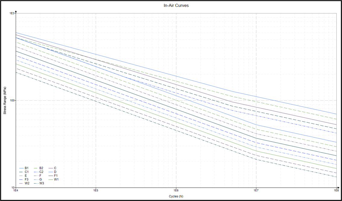
For the In-Air curves there is a new clause added to cap the C/C1 and C2 curves to a D-curve at the high stress range. This can be seen in the figure below, showing the base 25mm thick in-air curves:

Ground S-N Curves
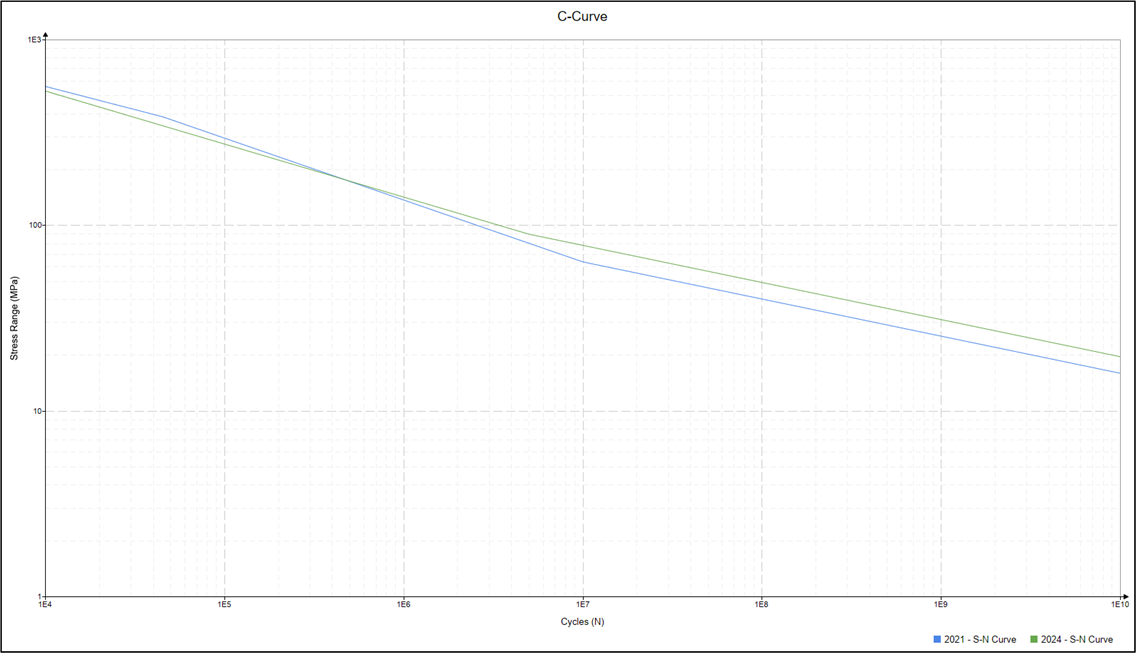
When looking at ground S-N curves, such as a C, C1 and C2 it is not as simple as producing a direct comparison of the previous 2021 curves to the revised 2024 version. This is because the grit blasting factor, a disbenefit applied to ground welds to account for the blasting required prior to coating, is now no longer required to be applied, but is inherent in the updated S-N curves.
To allow for a direct comparison “2021 to 2024”, we must apply the 2021 curve with an additional Stress Concentration Factor (SCF) to account for the grit blasting but not include it for the 2024 curves.
When producing this comparison plot for a C-Curve (see below), it can be seen they are very similar in the low cycle (high stress range) region but deviate in the high cycle. The figure is for 100mm plate thickness and in-air curves.
For a typical circumferential weld in a Monopile with a 40 MPa equivalent stress, there is a circa 3 times improvement in the endurance and thus damage.
This amendment implies that grinding of circumferential welds in Monopiles will be much more beneficial than the previous version of RP-C203.

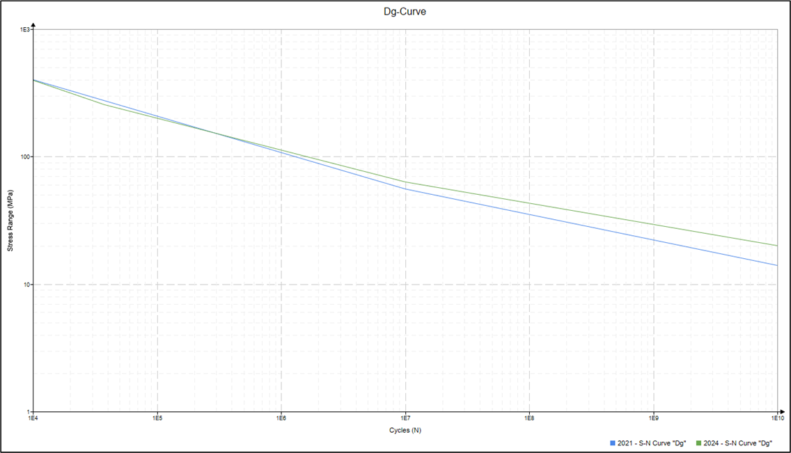
When looking at the revisions in Appendix F.14 for the alternative method of calculating fatigue damage from weld improvement a very similar comparison plot and improvement factor can be shown in the figure below. Again, this is for 100mm plate thickness and in-air curves.

Appendix F.16
The inclusion of Appendix F.16 is clearly the most interesting element of the updated code for Monopile foundations. It presents more appropriate curves to use for as-welded double sided butt welds in large diameter wind turbine structures.
There are, however, a few things to note. The curves as presented have no inherent misalignment (i.e. δ0 = 0). For reference, a D-curve has 0.05t inherent misalignment. So, to do a direct comparison, the F.16 curves need to account for the full misalignment, whereas a base D-curve does not. I.e. for F.16 the full misalignment (δm) must be applied through a use of an SCF.
One of the other key initial concerns with the F.16 curves is the requirement on the allowable maximum fabrication tolerance of “2 to 3mm” and limit to the weld cap angle. This does not align with most fabricators’ standard fabrication setup for Monopile cans which is set up to achieve a maximum misalignment of 4mm at the weld. This has been queried with DNV and if the weld cap angle limit can be achieved, there is no issue with having a misalignment of 4mm, so long as the applied SCF accounting for the misalignment is applied.
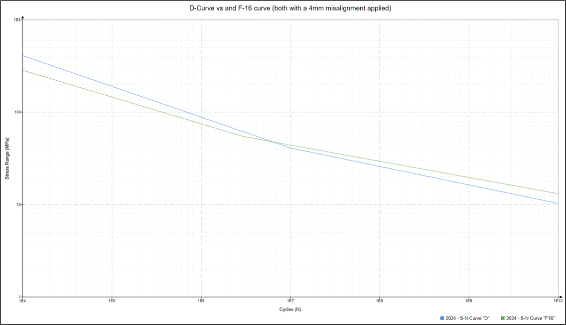
The figure below shows a direct comparison of the new F.16 curve with a base D-Curve (both for a plate thickness of 100mm, in-air curves). A misalignment (δm) of 4mm is applied to both curves.

Like the C and Dg curves, there is a benefit in the high cycle region. For a typical circumferential weld in a Monopile with a 40 MPa equivalent stress, there is a circa 1.5 times improvement in the endurance and thus damage.
However, in the low cycle (high stress range) region the F.16 curve is significantly more onerous than a D-curve. For an impact driving stress range (of 200MPa) there is a significant reduction in the endurance, circa 2.5x worse.
Closing Remarks
The update to the S-N curves for ground welds are clearly very beneficial. This poses several queries to the offshore wind industry:
- Should fabricators push to use grinding much more extensively?
- With the data from the F.16 curve in the low cycle (high stress range) region, do we really believe the predicted damage which will come from impact driving a ground circumferential weld?
- A cost comparison study of the increased fabrication cost for increased grinding vs the increased benefit from the new curves will be essential to get a feel for the lowest cost solution
It is not currently clear if the F.16 curves should be used as the default for circumferential welds. Given the revised physical tests carried out and that they are more applicable to use then there is some thought that they should be the default. There will be increased fatigue damage accumulation in these welds from impact driving of the monopiles, which to some degree will be offset by the improvement in the in-place damage. It is not clear yet whether overall there will be a net benefit or disbenefit to Monopile designs.
If you wish to discuss this topic any further or any other offshore wind foundation design topics, then do please get in touch.
Matthew Simms
Matthew Simms is a Chartered Mechanical Engineer in the Offshore Structures team at Wood Thilsted as well as a Fellow of the Institute of Mechanical Engineers (IMechE). He has over 19 years’ experience working on seismic, blast analysis and complex finite element modelling as well as offshore wind substructure design.
Wood Thilsted
Wood Thilsted is a specialised offshore wind engineering consultancy at the forefront of designing the global energy transition.
Driven by a shared purpose to accelerate the green energy transition, its team of world-class engineers delivers innovative, sustainable and optimised solutions that empower clients to achieve their renewable energy goals with greater speed and efficiency.
As a Certified B Corp, the company continues to push the boundaries of what it means to be a responsible business in the renewable energy industry.
For more information, visit www.woodthilsted.com/
DNV-RP-C203 Fatigue Design of Offshore Steel Structures
To access DNV-RP-C203 Fatigue design of offshore steel structures, visit https://www.dnv.com/energy/standards-guidelines/dnv-rp-c203-fatigue-design-of-offshore-steel-structures/
